Realistic Path Tracing (part II)
June 07, 2020
For starters, please first read my previous post, part 1, which describes some of the context regarding the construction of my path tracer. I left off last time with an incomplete glass renderer, so this is where the blog post picks up from.
Rendering Glass
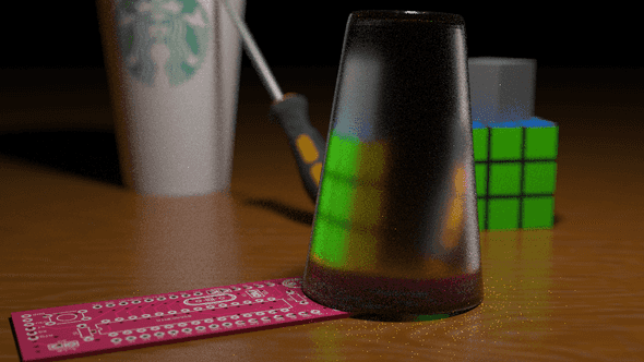
I began by trying to implement a glass BTDF based off of microfacet theory, as specified in my previous post. This led to the failing render:
After about a day and a half of tweaking variables to try to get it to work, I figured I would have to take a different approach. From what I could tell, the formulas for the PDF and evaluation functions I was implementing seemed correct, and the refractive directions I was sampling appeared to behave correctly depending on the mediums they were entering/exiting, so I wasn’t sure exactly what was going on. I decided to try a different approach.
Using Bram de Greve’s paper on refractive ray tracing, I tried to use a simpler approach. My teaching assistant, Andrew Bauer, suggested that I assume that the surface was ideally dielectric and work from there. This meant that I would:
- Assume that any refracted rays were ideally coming from a single,
perfectly refractive direction. Imperfect glass (e.g. glass with roughness) perturbs the refracted rays slightly, but that was not my focus.
- If a refracted ray originates from a single direction, then this would
imply that my sampling procedure returns that ray with probability 1 and other rays with probability 0. I choose then to ignore my PDF by setting it to 1 and then cancel out the BTDF cosine term using my evaluation function.
Despite this, I still needed to handle an important phenomenon when it comes to rendering refractive materials: total internal reflection (TIR). The basic idea behind total internal reflection is that if an incoming ray hits a material at a sufficiently grazing angle, the resulting outgoing ray will not actually be refractive, but rather, will be parallel to the surface and thus reflective. The angle at which this phenomenon occurs is known as the critical angle and is a property of the indices of refraction for both the incoming and outgoing mediums. For more information, please see the above paper or the Wikipedia entry on TIR.
Fortunately, this phenomenon can be modeled fairly compactly in a path tracer by making use the Fresnel coefficient, which in turn, can be generated using Schlick’s approximation. The Fresnel coefficient essentially yields a number between 0 and 1 that lets us select between reflection and refraction. A high Fresnel coefficient indicates a high amount of reflection; conversely, a low Fresnel coefficient indices a high amount of refraction. A Fresnel coefficient of 1 indicates total internal reflection (e.g. there is no refraction, only reflection). In path tracing, we can importance sample the Fresnel coefficient to select between a refractive and reflective incident ray. The algorithm works as follows:
- Keep track of incoming and outgoing indices of refraction. We can do
this by keeping track of the mediums the rays are in. 2. Calculate the dot product of the surface normal and the outgoing ray. 3. Use the cosine value and the IORs to calculate the Fresnel coefficient. 4. Importance sample the Fresnel coefficient to select between reflection and refraction.
In my case, I only had to keep track of two indices of refraction, the first being that of glass and the second being that of air. I choose to use 1.51 for Flint glass and 1.003 for air. In my previous attempts, I extended my payload to keep track of the order in which these indices appear, as it is important in determining the correct refractive ray.
I also swapped out my glass cup for a glass sphere, since it is easier to render and debug. The inside of the sphere is not hollow, but rather is assumed to be entirely filled with glass.
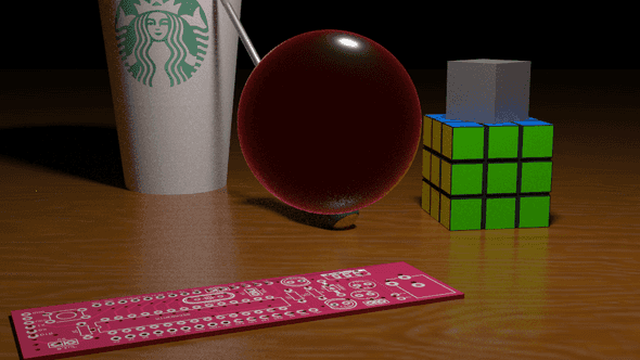
By rendering the intensity of the Fresnel coefficient as a shade of red on top of the diffuse version of the sphere, I got the following image. Note that I only accounted for Fresnel coefficients for rays originating from the camera:
As we can see, the Fresnel coefficient is extremely high around the edges of the sphere but is very low near the center of the sphere, where the rays hit perpindicular to the surface and are simply refracted through.
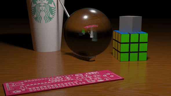
The next step is to implement the generation of the refractive ray. This can be done using the refraction formula listed in the above paper. With a few tweaks, I ended up with the following image:
Looks pretty good! You can see how the sphere acts as a lens, effectively inverting the rays passing through it. This is why the image appears upside down; this actually models real-world physical phenomena. See this discussion for more details.
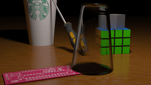
The final step is to bring back the more complex glass cup to replace the sphere.
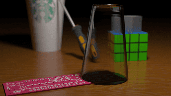
Ultimately, I was very satisfied with the glass rendering that I produced. I decided to leave it as an ideal dielectric surface and not tweak it any further using the GGX BTDF, since additional attempts to incorporate the BTDF ended in failure. Unfortunately, it took me around three days to finally get this to work, which ate into the time I had allotted for rendering participating media using volumetric path tracing.
You’ll also notice that the area covered by the glass seems shadowed, and that is in part because next event estimation does not work through glass (direct light through glass does not account for refracted rays; it’s treated as if it is a solid object during the estimation).
Rendering Participating Media
For the final step of my project, I choose to render some form of a homogeneous participating medium that will surround most of the scene. Unfortunately, due to the unforeseen amount of time that the glass implementation took, I was unable to complete it in a visually appealing manner. However, I will still document the implementation details, even though it did not contribute to my final render. The following resources were helpful in my implementation: the smallvpt renderer, a modification of the smallpt renderer to support volumetric path tracing, as well as this Stack Exchange post on volumetric path tracing.
In order to implement a partipicating medium, you need to use volumetric path tracing. Volumetric path tracing extends the rendering equation with additional terms that describe how a ray moves through a semi-transculent container of particles. For this project, I assumed that the particles were homogeneous, in that they were evenly dispersed through the volume.
Whenever a light ray passes through this volume, there are 3 situations that can occur:
- Nothing happens, the ray passes through as normal.
- The ray hits one of the particles and is absorbed.
- The ray hits one of the particles and is scattered.
These frequency of these events occurring are given by two probabilities: the scattering probability and the absorption probability. The scattering probability is a function of both the distance the ray must travel through in the medium and a constant dependent on the medium, known as . Likewise, the absorption probability is a function of the distance the ray must travel and a constant that acts as a property of the medium (). Both of these probabilities are given as exponential functions that converge to 1 with respect to distance; that is, as the ray travels through the medium, a longer distance implies a smaller chance that the ray will make it through unscathed (not reflected or absorbed).
In the case where the ray is absorbed, the ray can simply be stopped and contribute a reduced amount of radiance.
In the case where the ray is scattered, a new direction and origin has to be computed for the incident, scattered ray. The origin of this ray is usually given by picking a random “scatter point” that lies in between the first surface that the original ray intersects with and the original origin. The direction of the new ray is a bit more complicated. This is where phase functions come into play, which describe how rays are scattered in the participating medium. I choose to use the Henyey-Greenstein phase function to describe my medium.
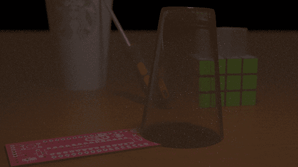
Using this algorithm, I was able to produce the following image:
As you can see, the scattering of the rays is producing noticeable darkening, as well as visible blurring that complements the depth-of-field effect. This is an intended effect, as fog/smoke often results in the same. However, the image was too noisy and even with tweaking, still did not capture the realistic fog effect I was intending to recreate, and without enough time to modify it any further, I decided to drop the effect from my final image. Despite this, I would still like to potentially work on this as an improvement to my image in the future.
Final Remarks
Given that the participating media render didn’t look as realistic as I would have liked it to look, I ultimately decided to drop the fog/smoke effect from the final render. Here is the final scene rendered, with depth-of-field added back in and with 1024 samples per pixel (instead of the usual 64):
Ultimately, this was a very enjoyable project and, in my opinion, was a successful end to a very enjoyable class. I hope to work more with rendering in the future, perhaps continuing with a real-time path tracer outside of the CSE 168 class.
